Earthing is defined in BS 7671 as the connection of exposed conductive parts of an installation to the main earthing terminal of that installation. Whilst this may be a useful definition, it does not fully encompass the full meaning of earthing, bonding and automatic disconnection of supply.
BS 7671 contains much detail on earthing systems and selecting protective and earthing conductors of suitable size such that they will remain effective during a fault. Within this aspect of earthing there is an intent to provide a low impedance path to exist such that sufficient fault current will flow to allow protective devices to operate in a timely manner and make faulty circuits safe. With regards to design criteria, when selecting conductors the intent is to select conductors that are:
- of sufficient cross-sectional area to provide a low enough impedance in relation to fault current
- of sufficient cross-sectional area to avoid damage when fault-current flows
- is robust enough so as not to deteriorate, taking into account installed conditions.
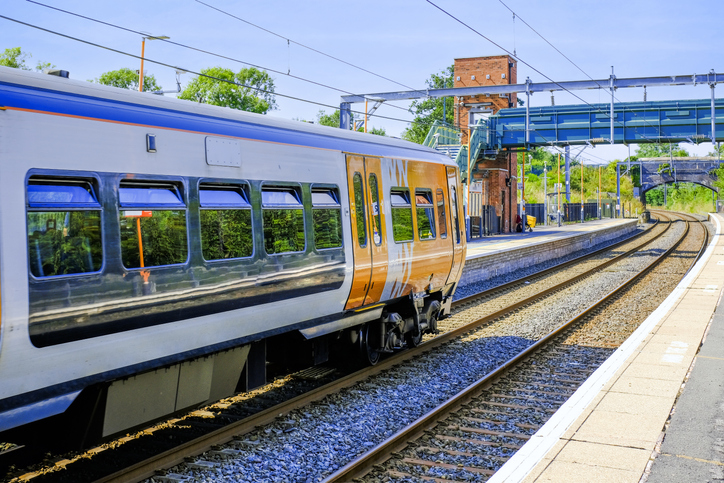
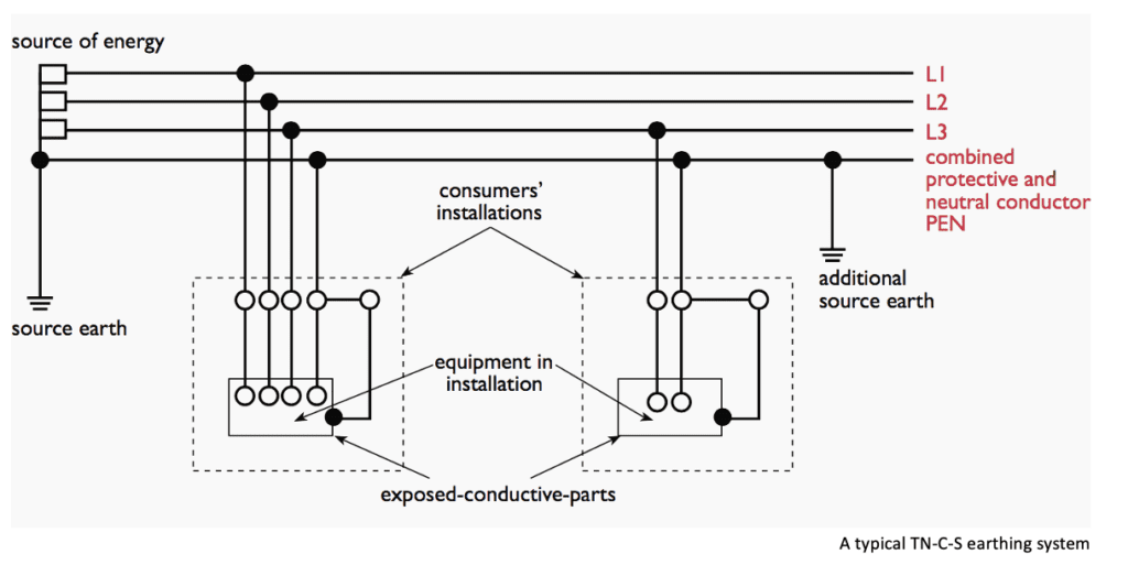
For many electrical systems, the supply will originate from a Low Voltage Distribution Network Operator (DNO) supply and they will provide a connection with earth; typically this will be an earth connection that runs separate to the neutral on their system (TN-S), or more commonly with newer supplies, an earth connection that is connected to their supply cable neutral (TN-C-S). In some instances, where the DNO cannot provide a reliable earth, they may not provide an earth connection, and will require the consumer to provide their own earth connection using an earth electrode (TT).
Where the DNO provides an electrical supply from a Low Voltage (LV) public system, the requirements and design criteria are rarely complicated.
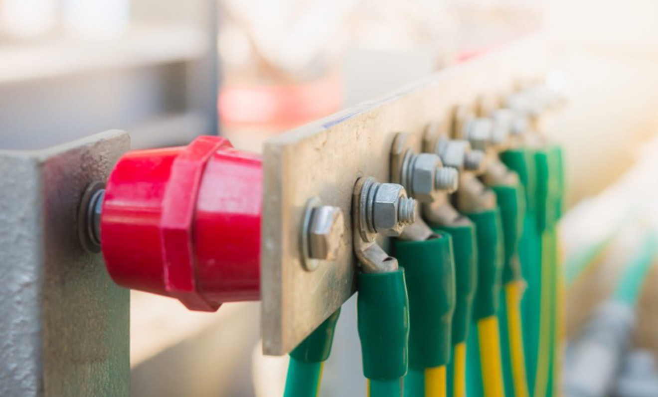
Reference is made to bonding, this is the interconnections of exposed conductive parts Metal parts of electrical equipment) and extraneous conductive parts (metal parts associated with non-electrical systems such as structural steelwork, water and gas service pipes, and lightning protection systems, Where earthing is concerned with providing a low impedance fault-path for current to flow, bonding maintains an equal and low risk potential difference between electrical and non-electrical parts, and prevent unacceptable voltage rise which could otherwise introduce shock risks both under fault conditions and in normal use.
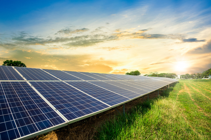
For those who generate their own supply of electricity, and those who take their supply at High Voltage (HV), the responsibilities for earthing become a little more complex. Again BS 7671 offers some guidance in recognising that the interconnection between HV earthing systems and LV earthing systems needs to be carefully considered, as there is a risk that under fault conditions on one system, dangers may be introduced onto the other system, and the potential for circulating earth currents will increase. In some instances, it is safer for HV and LV earthing systems to be directly connected, whereas separating HV and LV earthing systems may eliminate some issues whilst introducing others.
For these ‘private’ systems, the need to design and maintain an effective and safe earthing system falls to the client, this includes a reliable connection with earth at the supply transformer or generator and may require different approaches dependant on how the electrical system is configured. BS 7430:2011+A1:2015 is the Code of Practice for protective earthing of electrical installations, BS EN 50522:2010 is the standard relating to earthing of power installations exceeding 1 kV AC. Harmonised Document HD 60364-5-54:2011/ A11:2017 deals with Earthing arrangements and protective conductors.
HV systems present additional risks due to the potential for circulating earth currents through the general mass of earth, both during normal use and during a fault, there are risks from ‘touch potential’ whereby a person may receive a shock from coming into close contact with a metal part and the general mass of earth or from ‘touch potential’ whereby a hazardous voltage might exist where a person walks across a surface. There are many methods employed to control these phenomena’s, which must be maintained to remain effective.
There are circumstances where electrical systems may not be earthed, or the connection with earth is through an intentionally high impedance. On HV systems this will usually be via a neutral earth resistor which restricts earth fault currents to a low value, this will be in association with protection relays that should detect earth faults and disconnect the supply before unsafe conditions are realised.
For LV systems the use of systems connected to earth through a high impedance is less common but is used as a protective measure in specific situations, typically where it is essential to maintain a supply of electricity. An example of this would be the electrical supply to a medical operating theatre. In this case an intentional high impedance is introduced into the transformer earth connection and monitoring devices are used to indicate when a fault exists. This is an IT earthing system.
In this case the supply of electricity remains, the flow of current to earth is minimal, and a co-ordinated plan can be put in place to resolve the situation or move to a ‘fault-free’ location. If a second fault occurs on the system, the power supply will automatically disconnect without any further warning.
So far, alternating current (A.C.) systems have been considered, however earthing of direct current (DC) systems is undertaken in the same way. Within the UK most AC LV supplies originate from a three-phase star-connected transformer, and the star point is connected directly to earth. For DC systems it is the mid-wire that is often connected to earth. For single phase AC LV systems, the neutral is normally connected to earth, for DC two wire systems it is often the negative that is earthed.
Special consideration must be given to the type of earthing systems employed where increased risks exist, for example where there is a potentially explosive atmosphere or where swimming pools exist, and the dangers of circulating earth fault currents could pose a serious risk. Locations where caravans or metallic structures such as greenhouses exist and those structures are connected to the electrical earthing system, shock risks will be introduced if the system earth becomes defective. In general, the use of TN-C-S earthing systems is prohibited in these circumstances.
Electric Vehicle (EV) charging units present similar issues when TN-C-S earthing systems are used. A novel approach has been taken to deal with the risks that are presented, with neutral earth monitoring devices being introduced and if issues are detected the whole of the supply, including neutral and earth connections are disconnected.
Maintenance earthing systems is very important, and this includes the connections made with earth, the conductors used to connect exposed and extraneous conductive parts to the means of earth and protective devices that operate to safely disconnect the supply in the event of a fault. For LV installations this will normally be based on Part 7 of BS 7671- inspection and testing, in which the continuity of protective conductors is measured, the earth fault loop impedance at the end of circuits and at switchgear is determined and the results verified against the standards.
For more complex earthing systems, maintenance will become more complex, and an Earthing Study would be a good starting point to ensure that the existing system is compliant and functional. It is also recommended that a Protection and Co-ordination Study be carried out to ensure that protective devices meet the desired requirements. The effectiveness of earth electrodes must be confirmed on private systems, including their effectiveness when the electrical system is configured to be supplied from non-routine sources such as a standby generator or an interconnector.