
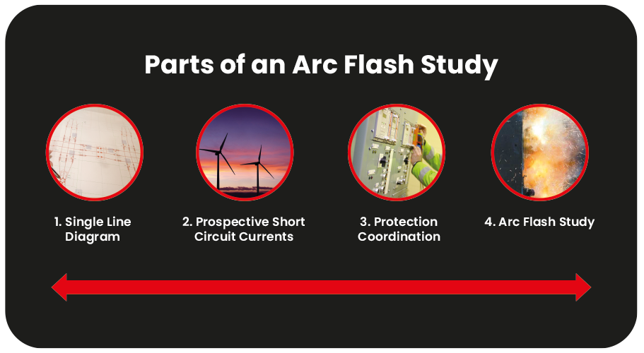
We often get asked, why do arc flash studies matter when there are no prescriptive standards in place in the United Kingdom? Well, one good reason is, the majority of things that we would need to do when carrying out an arc flash study, are things we should have been doing for years before AF studies were even thought about. The study is made up of four parts and it can be argued that each one of these parts can be described as a requirement of present UK and European legislation and associated guidance. The four parts that we are speaking about are:
- The provision of a single line diagram of the electrical system
- The calculation of prospective currents
- The coordination of protection arrangements
- Finally, the arc flash study which, when combined with parts 1,2 and 3 above is a fraction of the total effort required.
Sadly, we often encounter situations where none of the above have been provided for in a way that would be termed satisfactory. So, lets go through each one individually and explain how each one is important.
Part 1: The provision of a single line diagram of the electrical system.
We can surely agree that having an up-to-date single line diagram of an electrical system is essential for the purpose of safe isolation practices, especially in the case of emergencies. In fact, the Electricity at Work Regulations 1989 Regulation 12 states “(1) Subject to paragraph (3), where necessary to prevent danger, suitable means (including, where appropriate, methods of identifying circuits) shall be available for –
- cutting off the supply of electrical energy to any electrical equipment
- the isolation of any electrical equipment.”
Regulation 12 is known as an “absolute regulation” which means that it must be met regardless of time, cost, and effort.
Part 2: The calculation of prospective currents in an electrical system.
Electricity at Work Regulations 1989 Regulation 5 states: “No electrical equipment shall be put into use where its strength and capability may be exceeded in such a way as may give rise to danger.”
The calculation of prospective currents in an electrical system is necessary to understand if the component parts of that system could be overstressed either in normal, emergency or switching operations. In other words, to determine where the strength and capability of those parts may be exceeded in such a way as may give rise to danger.
Part 3: The coordination of protection arrangements
A poorly coordinated electrical system may be seen at first as purely of nuisance value but, implicit in Regulation 11, means for protecting from excess of current, from the Electricity at Work Regulations, there is a requirement for protection coordination to be properly designed. As Regulation 11 states “Efficient means, suitably located, shall be provided for protecting from excess of current every part of a system as may be necessary to prevent danger.” Reasons are given below for why electrical protection must be properly chosen and installed in accordance with good electrical engineering practice which includes coordination.
- Relying on upstream devices that are not local for fault clearance could mean that unnecessarily high fault currents may be required to protect downstream circuits and equipment. The words “suitably located” could be interpreted in most cases as being necessary to ensure that devices operate that are nearest to the fault.
- The unnecessary disconnection of parts of an electrical system may create danger in other ways for instance, essential supplies in a hospital or any other facility.
Part 4: The arc flash study
The Memorandum of Guidance on the Electricity at Work Regulations 1989 (HSR 25 Paragraph 44) states “Under fault flashover (arc flash) conditions, currents many times the nominal rating or setting of a protective device may flow before those devices operate to clear the fault. Much energy is dissipated in the arc and depending on the electrical protection, may continue long enough to inflict very serious arcing burns or to initiate a fire in periods for example as short as 0.25 second, which is not an untypical minimum time for fault clearance. Arc flashovers caused during work on live circuit conductors are likely to be particularly hazardous because the worker is likely to be very near to or even enveloped by the arc. Such cases often lead to very serious, sometimes fatal, burn injuries.”
From the above statement, an arc flash study to the latest standards will allow for the determination of five key benefits that were not possible when HSR 25 was first written.
- Benefit 1: The amount of current that will flow in the arc.
- Benefit 2: The severity of the thermal effects of the flashover or arc flash at the worker who may be working on or near or operating the electrical equipment in question.
- Benefit 3: The distance at which the severity of the thermal effects of an arc flash will attenuate to a safer level. (Arc Flash Boundary)
- Benefit 4: The protection arrangements that will be required to reduce the severity to a safer level.
- Benefit 5: The personal protective equipment that may be required as a last resort principle must involve an analysis and assessment of risks which cannot be avoided by other means. Regulation 4:4 from Systems, work activities and protective equipment states: “any equipment provided under these Regulations for the purpose of protecting persons at work on or near electrical equipment shall be suitable for the use for which it is provided.”
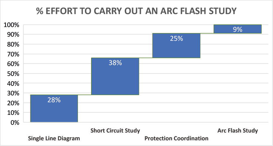
Finally, 90% of the effort for a study is what we should be doing anyway and unless Parts 1,2 and 3 are in place and are fully compliant. When carrying out system studies, most of the basic electrical system information gained is what any self-respecting electrical engineer ought to have at his or her fingertips. As stated above, a precursor to an arc flash study is to have a single line diagram of the electrical system, a short circuit study and a protection coordination study. Appendix A from IEEE 1584 2002 described all the data that would be required to undertake an arc flash study. It broke the data down into four separate categories: 1. The diagram, 2. Short circuit study, 3. Coordination study and 4. The arc flash study. From this document, this is represented into a chart shown below.
Conclusion
Most information to undertake an arc flash study is what engineers who have responsibilities for an electrical installation will choose to keep anyway. Most would feel uncomfortable as duty holders if they did not have these records in place. This is just one reason to undertake an arc flash study out of a total of ten good reasons that have been identified in the book The European Arc Flash Guide by our own Mike Frain CEng FIET MCMI.